1. Structura generică a unui device IoT. Arhitectura generală, definiții și descriere componente
Internet of Things - IoT (Internet of Things) or Internet of Everything - a network of objects that incorporates electronic circuits that allow communication through existing infrastructure for the purpose of remote monitoring or control.
An embedded system is a a combination of a computer processor, computer memory, and input/output peripheral devices that has a dedicated function within a larger mechanical or electrical system.
An Embedded System is a device or equipment made by engineering in various fields such as Mechanical Engineering (ME), Electrical Engineering (EE), and Software Engineering (SWE).
Architecture refers to the fundamental structures of a system and the discipline of creating such structures and systems. Each structure comprises software or hardware elements, relationships between them and properties of both the elements and the relationships.
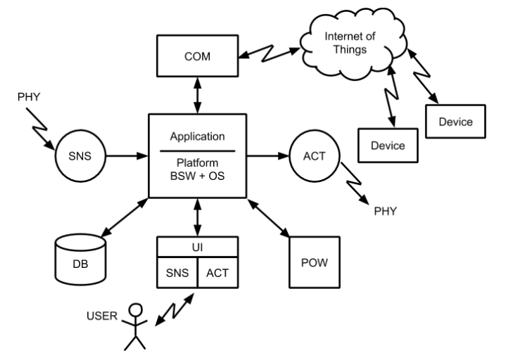
Components:
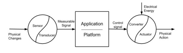
- Sensors - the totality of components that participate in the transformation of a signal from the external environment, represented by a physical quantity (PHY) into an internal signal of the system
- Actuators - the totality of components made that participate in the transformation of a signal inside the system into an action on the external environment, represented by a physical quantity (PHY).
- Microcontroller where the application/ Operating System run - Operating systems represents the resource management mechanism of a computing system such as memory, peripherals and processing time.
- User Interface - represents all the components that facilitate the interaction with the system user.
- Communication - the way to exchange information between involved actors.
- Power supply
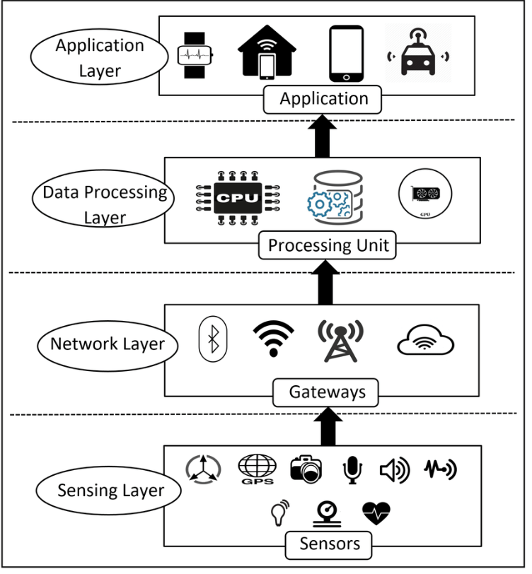
Architecture layers:
- Sensing Layer: physical devices equipped with sensors that collect data from their environment and transmit this information for further processing.
- Network Layer (Connectivity Layer): responsible for transmitting the data collected by the device layer to the next processing units. It consists of communication protocols and network infrastructures
- Data Processing Layer: where data undergoes initial processing and analysis.
- Application Layer: user interfaces and application-specific functionalities.
Classification:
- Cloud-based architecture - data is stored and processed in cloud servers
- Edge-based architecture - data is stored in devices themselves (usually done when the internet connection is not that strong)
- Hybrid - combines the advantages of cloud and edge architectures. data is processed in cloud and in the devices, based on the situation.
Interactions within the system:
- User Interaction
- Environment Interactions
- Device Interactions
2. User Interaction - general notion, classification and types of interfaces (binary, arrays), I/O STDIO, complex interfaces
The user interface represents all the components that facilitate the interaction with the system user. As a rule it represents a collection of specialized sensors and actuators.
Categories:
- Binary interfaces,
- One and two dimensional grid interfaces,
- Standard STDIO input / output interface
- Complex interaction interfaces.
- Digital Interface
- Analog Interfaces
Binary Interfaces Simplest form: 1x1 key, 1x1 pixel Examples:
- Single button input
- Single LED output
- Basic on/off states
- Direct digital I/O control
Arrays Expanded binary: Multiple inputs/outputs Keypad Systems (4x4 matrix scanning) LED Arrays (7-segment displays, LED matrices (8x8, 16x16))
Digital Interfaces Character-based displays and input (LCD displayes, text-based interactions)
STDIO
- universal hardware abstractions - there are standardized functions (e.g. scanf/prinft) that can be linked with various input/output devices
Analog (continuously valued interactions) for input: analog sensors - potentiometers, sensors, pressure/temperature sensors for output: pwm brightness control, servo motor positioning
Advanced Interactions
- Voice speakers and assistants
- camera-based input systems (recognizing gestures etc.)
- Augmented reality (digital overlay over the real world )
- Virtual Reality (Immersive digital worlds)
All these interactions are based on various communications methods. Wired:
- Serial/UART (point to point)
- I2C between devices Wireless
- Wifi
- Bluetooth
- Zigbee (type of mesh networking)
3. Sensors - general notions, classification, signal acquisition, signal conditioning, signal processing/filtering
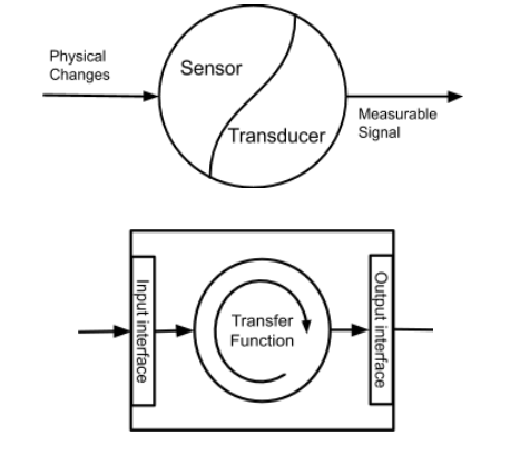
The sensors - the totality of components made by software engineering (SW), electrical engineering (EE) and mechanical engineering (ME) that participate in the transformation of a signal from the external environment, represented by a physical quantity (PHY) into an internal signal of the system
So, sensor - senses change in the environment and transforms into measurable value; Transducer - converts measurable value into electrical signal
| Feature | Human | Device |
|---|---|---|
| Senses | Sight, Smell, Hearing, Touch, Taste | Temperature, Humidity, Sound, etc. |
| Mechanism | Biological | Electronic/Mechanical |
3. Sensor Components
- Sensor: Detects physical change in the environment.
- Transducer: Converts measurable values into electrical signals.
II. Sensor Classification
1. Parameter Kind:
- Examples: Temperature, Humidity, Pressure, Light, Sound, Rotation, Magnetic Field, GPS, Acceleration.
2. Interface Type:
- Binary: On/Off, HIGH/LOW (Digital 0 or 1).
- Analog: Continuous range of values.
- Digital Communication: PATA, LPT, PORTA, SPI, I2C, USB
3. Signal Source
- Enteroceptive (Internal): Monitors internal system characteristics (e.g., CPU temperature).
- Exteroceptive (External): Measures parameters in the environment.
4. Localization:
- Local: Measures within the system’s immediate environment.
- Global: Gathers information from a broader area.
5. Active vs. Passive:
- Active: Emits energy (e.g., ultrasonic sensor) to measure.
- Passive: Detects existing environmental signals. (e.g Temperature Sensor)
6. Classification Criteria Table
| Criteria | Local Examples | Global Examples |
|---|---|---|
| Internal | Battery Sensor, Chip Temp. Sensor | hi- |
| External | On-board Camera, Resistive TouchSensor | Overhead camera, Satellite GPS |
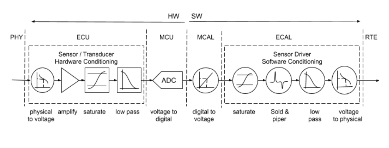
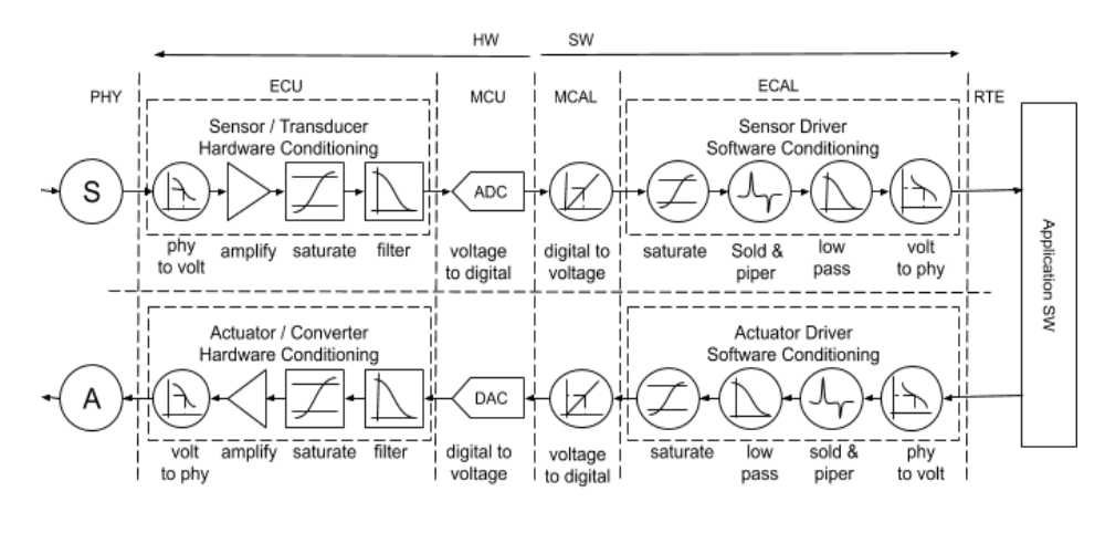
III. Signal Acquisition
The process of converting a physical quantity into an electrical signal. It often involves several signal processing blocks, like Hardware/Software filters.
Information – Data with means
- Physical Environment: The source of the signal.
- Sensor Service: Provides interface for upper layers and Sensor connection. (Signal Conditioning, Diagnosis)
Signal Conditioning
1. Definition:
The manipulation of a sensor signal to prepare it for processing. Can be done through HW and SW
2. Hardware Conditioning:
- Amplification/Attenuation: Adjust signal strength. (using Resistor schemes, OPAMPs)
- Filtering:
- Low-Pass: Allows low frequencies. (RC schemas, RLC)
- High-Pass: Allows high frequencies. (RC schemas, RLC)
- Band-Pass: Allows specific range of frequencies. (RC schemas, RLC)
- Saturation: Limit signal amplitude.(using diodes)
3. Software Conditioning:
- Signal Saturation: Set max and min ranges for values.
- Filtering: Applying mathematical operations to remove noise.
V. Signal Processing and Filtering
1. Goal:
Enhance or extract information from the raw sensor signal.
2. Analog Filters
- Passive: Using resistors, capacitors, inductors.
- Active: Using OP-AMP to enhance signals
3. Digital Filters
A. Statistic Filters:
- Median Filter: Replaces each value with the median of neighborhood values.
- Salt and Pepper Filter: Removes impulse noise (black and white pixels). It works by replacing each data point with the median value of its neighbors within a defined window, effectively eliminating outlier values.
B. Average Filters:
- Weighted Average Filter: Each data point is multiplied by a weight coefficient.
C. Conversion Techniques
- Linear Conversion: ( y = ax + b) to normalize a signal
4. Actuators in Embedded Systems: A Comprehensive Summary
I. General Notions
1. Actuator Definition
Actuators - the totality of components made by software engineering (SW), electrical engineering (EE) and mechanical engineering (ME) that participate in the transformation of a signal inside the system into an action on the external environment, represented by a physical quantity (PHY).
2. Actuator Role
- Receives a control signal.
- Involves a converter: transforms electrical energy to a suitable form.
- Produces physical action/output.
II. Actuator Classification
Actuators can be classified based on several criteria:
1. Parameter Nature
What kind of physical parameters the actuator can act upon.
- Temperature, Humidity, Pressure, Light, Sound, Rotation, Position.
2. Actuator Interface
How the control signal interfaces with the actuator:
- Binary (Digital): On/Off states.
- Analog: Continuous control signals.
- Digital Communication: Serial protocols (SPI, I2C).
- Time Based : Uses Pulse width modulation techniques.
3. Action Target
-
Internal Action:
-
Affects parameters inside the embedded system itself (e.g., CPU cooling fan).
-
External Action:
-
Affects parameters in the external environment (e.g., controlling room temperature).
4. Actuator Location
Where the action occurs (important in distributed systems):
- Local: Action occurs within the immediate system’s vicinity.
- Global: Action has wide-reaching effects or occurs at a distance.
5. Feedback
- Closed Loop: Uses sensors to monitor output and adjust the control signal (precise, stable).
- Open Loop: No feedback; the actuator operates based on the control signal alone (simpler, less accurate).
III. Functionality - Actioning Methods
Actuators realize specific actions on the environment. The main types include the following, with examples for each type:
1. Power Conversion (Electrical control signal to Energy)
- Transistor - Analogy: Transistors are fundamental to how you send the Electrical signal to the system.
- Power conversion - Relay: Act as electrical switch between low voltage (control signals) and high voltages needed for actuators.
- Power Conversion - Analog control: use operational amplifiers, but are expensive and hard to handle with embedded systems.
- Transistor - Power dissipation (heat): When transistors change stages (open - close) can have energy/power loss and need to use snubber diodes
2. Power Conversion - Commutation
- Uses PWM (Pulse Width Modulation) to produce better energy efficiency
3. Power Conversion - H Bridge
- Use H Bridges to control motor direction with electronic components.
- Enable precise positioning when combines with BLCD (brush less dc motor)
- Use H Bridge for Stepper motors, and allow precise stepping.
IV. Signal Generation
1. Overview
A sensor sends back a signal, and an internal system must act upon the enviroment, which most of time means generate another signal.
2. Signal Generation (Software)
- To drive multiple devices:
- Need to implement a Layered architecture and divide it between services
- Each layer and service has specialized function
5. Sequential Systems - elaboration principles, functioning principles, planning of task execution
Sequential systems execute tasks one after another in a fixed order without interruption. Each task runs to completion before the next begins.
Unlike preemptive systems, sequential systems rely on cooperative task execution and scheduling patterns.
Deterministic Execution
- Tasks always execute in same order
- Predictable timing patterns
- No task interruption
- Single execution thread
Cooperative Multitasking
- Tasks voluntarily return control
- No forced task switching
- System can hang if task doesn’t yield
- Simple synchronization
Execution Models
Simple Loop
- Fixed task order
- Equal time allocation
- Easy to implement
- CPU Load: 100%
Event-Driven
- Tasks execute only when needed
- Better power efficiency
- More responsive
- CPU Load: < 100%
Time-Sliced
- Fixed time per task
- More predictable timing
- Requires timer mechanism
Task Planning
Timing Analysis
- Loop Time = Sum of all task execution times
- Response Time = (task_position - 1) × Loop_Time + Task_Time
- CPU Utilization = Total_Task_Time / Loop_Period × 100%
Scheduling Strategies
- Fixed Priority: Critical tasks first
- Rate Monotonic: High frequency = high priority
- Round Robin:- a preemptive scheduling algorithm where each task gets an equal, fixed amount of CPU time called a “time slice” or “quantum.” Tasks are executed in circular order.
Task A (10ms) → Task B (10ms) → Task C (10ms) → Task A (10ms) → ...
How It Works
Basic Concept
- Each task gets same time slice (e.g., 10ms)
- When time slice expires, current task is preempted
- Next task in queue gets CPU
- Preempted task goes to end of queue
- Process repeats in circular fashion
Advantages:
- Simple to understand and debug
- Predictable behavior
- Low memory overhead
- Deterministic timing
Limitations
- Poor responsiveness
- One slow task blocks all others
- No real-time guarantees
- Difficult to scale
Problems:
- Need for real-time response
- Multiple concurrent functions
- User interaction requirements
- Complex communication protocols
When to use
- Simple control applications
- Basic sensor reading
- LED/display controllers
- Learning/prototyping platforms
Best practices
- Keep tasks short
- Avoid blocking operations
- Implement watchdogs
- Measure execution times
- Plan for worst-case scenarios
Problems:
- Spin locks waste CPU cycles
- Unresponsive tasks block system
- Poor real-time performance
6. Communication Between Systems: A Comprehensive Summary
I. Communication Definition
Core Concept
Communication involves the exchange of information between involved actors (systems).
Key Elements
- Message: The information being transferred.
- Transmitter: The sender of the message.
- Encoding: Converting the message into transmittable format.
- Channel: Medium through which the message travels.
- Decoding: Converting the received signal back into message.
- Receiver: The destination system.
- Feedback: Information sent back from receiver to sender, verifying or acknowledging that the delivery was well.
- Noise: Interference that can degrade the message during transfer.
II. Communication Environment
Classification based on Media:
- Wired
- Electrical: Uses copper wires (e.g., Ethernet).
- Optical: Uses fiber optic cables.
- Wireless
- Optical: Uses light (e.g., infrared).
- Sound: Uses sound waves.
- Electromagnetic: Uses radio waves (e.g., WiFi, Bluetooth).
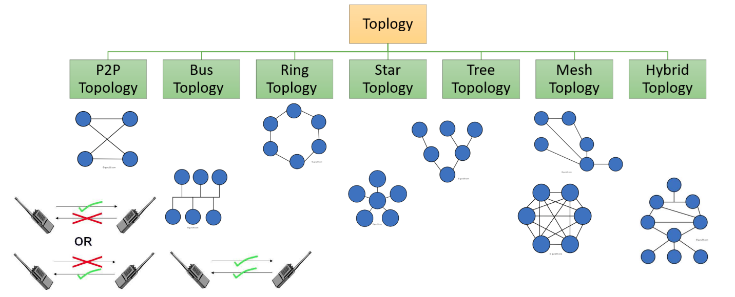
III. Network Topology
Arrangement of how devices are interconnected in a network:
-
P2P Topology: A system or network in which individual components can communicate directly with each other
-
Bus Topology: A bus topology is a network configuration where all devices are connected to a central cable or line.
-
Ring Topology: a type of network topology in which each device is connected to exactly two other devices, forming a single continuous pathway for signals through each node.
-
Star Topology: is a network setup where each device or node is independently connected to a central hub, switch, or computer.
-
Tree Topology: A tree topology combines features of bus and star topologies, connecting multiple star networks via a central bus.
-
Mesh Topology: a network setup where each device is interconnected with many other devices, creating multiple paths for data transmission
-
Hybrid Topology: Combines two or more topologies in a network design
-
Half Duplex: One direction at a time
-
Full Duplex: In both directions
IV. Communication Protocol
Definition
A set of rules agreed upon by communicating systems to ensure reliable and secure information transfer.
ISO/OSI Reference Model (7 Layers)
- Application Layer: User-facing protocols (HTTP, MQTT).
- Presentation Layer: Data representation (encryption, compression).
- Session Layer: Managing connections.
- Transport Layer: Reliable data transfer (TCP, UDP).
- Network Layer: Routing between networks (IP).
- Data Link Layer: Frame-based transmission (Ethernet).
- Physical Layer: Physical medium and signal transmission.
V. Hardware Protocols
1. Serial Communication
Transmit data bit by bit. Uses fewer wires but is slower.
- USART
- SPI
- I2C
2. Parallel Communication
Sends multiple bits simultaneously. Uses more wires for faster transmission.
3. Wireless
- Wi-Fi (IEEE 802.11)
- Bluetooth
- Zigbee
VI. Hardware Protocol Specifics
1. Serial Peripheral Interface (SPI)
- Full Duplex: Data can be transmitted and received simultaneously.
- Master-Slave Architecture: One device (the master) controls all other devices (slaves).
- Multi-Slave Support: Requires a separate Slave Select (SS) line for each slave device.
2. Inter-Integrated Circuit (I2C)
- Two Wires Only: Serial Data (SDA) and Serial Clock (SCL).
- Addressing: Each device on the bus has a unique address.
- Multi-Master Support: Multiple devices can initiate communication (though collision management is needed).
Example: A microcontroller needs to read temperature and humidity values from a DHT22 sensor.
3. Universal Asynchronous Receiver/Transmitter (UART)
- Asynchronous: No clock signal is shared.
- Simple Two-Wire Interface: Transmit (Tx) and Receive (Rx).
- Start and Stop Bits: Used for synchronization. Scenario: A microcontroller wants to send debugging messages to a computer for monitoring.
VII. Software Protocols
Specify data formatting and transmission rules at the higher layers.
- UART: A bare bones method of transmission.
- TCP/IP : The Transmission Control Protocol/Internet Protocol.
VIII. Data Transmission on the Cloud with MQTT
1. Message Queuing Telemetry Transport (MQTT)
- Lightweight publish-subscribe protocol.
- Designed for IoT devices with limited resources.
- Reliable message delivery using TCP.
2. Key MQTT Concepts
- Broker: Central server that routes messages.
- Publisher: Device that sends messages.
- Subscriber: Device that receives messages by subscribing to topics.
- Topic: Categorical label for messages (e.g., “sensor/temperature”).
# Finite State Machines (FSMs) in Embedded Systems: A Summary
A Finite State Machine (FSM) is a mechanism that changes its states in reaction to system inputs and produces corresponding outputs.
Core Concepts
- A mathematical model of computation.
- Represents the behavior of a system as transitions between distinct states.
- Useful for designing systems with well-defined, sequential behavior.
- A model of behavior composed of states, transitions, and actions.
II. Defining Characteristics
- Finite Number of States: The system can only be in a limited number of configurations. One must be defined as the initial.
- Finite Number of Inputs: The system receives a fixed set of external stimuli.
- Finite Number of Outputs: The system generates a limited set of responses.
- Transfer Function: Rules dictating how the system transitions between states based on inputs.
- Output Definition Function: Defines what output is produced in each state.
- A state stores information about the past, it reflects input changes.
Key Terms
- State: A distinct situation/configuration.
- Transition: Change from one state to another.
- Event: Input triggering a transition.
- Action: Activity performed.
- Initial State: Starting state.
- Final State: (Optional) Ending state.
FSM Diagram (Mermaid)
stateDiagram
  [*] --> Idle
  Idle --> Active : Button Press
III. FSM Types
1. Mealy Machine (Immediate)
- Outputs depend on the current state and the current inputs.
- Changing inputs immediately impact the outputs.
- The next state depends on the current state and the current inputs.
2. Moore Machine (Delayed)
- Outputs depend solely on the current state.
- Changing inputs do not immediately impact the outputs. There is an implicit delay.
- The next state depends on the current state and the current inputs.
IV. Key Differences Summarized
| Feature | Mealy Machine | Moore Machine |
|---|---|---|
| Output Dependency | Current State AND Input | Current State ONLY |
| Output Timing | Immediate, changes with Input | Delayed, only changes at state transition |
| Complexity | Can be more compact and reactive | Simpler to understand and analyze |
V. Practical Implementation (Arduino Example)
#define LED_PIN     2
#define BUTTON_PIN  8
#define LED_OFF_STATE  0
#define LED_ON_STATE   1

struct State {
  unsigned long Out;     // Led State
  unsigned long Time;   // delay in 10ms units
  unsigned long Next [2];   // next state for inputs 0,1
};
typedef const struct State STyp;

//FSM initialization (only one time)
STyp FSM[2] = {
  {0,10, {LED_OFF_STATE, LED_ON_STATE }},
  {1,10, {LED_ON_STATE, LED_OFF_STATE }}
};

int FSM_State = LED_OFF_STATE;
void setup() {
  // Init Button
  pinMode (BUTTON_PIN, INPUT);
  // Init LED
  pinMode(LED_PIN, OUTPUT);
  // Init Initial State
  FSM_State = LED_OFF_STATE;
}

// The loop function is called in an endless loop
void loop() {
  // 1. Output Based on current state
  int output = FSM[FSM_State].Out;
  digitalWrite(LED_PIN, output);

  // 2. wait for time relevant to state
  delay(FSM[FSM_State].Time * 10);

  // 3. Get Input
  int input = digitalRead(BUTTON_PIN);

  // 4. Change state based on input and current state
  FSM_State = FSM[FSM_State].Next [input];
}
8. Functional Control
I. Control Definition
Control Functional in embedded systems refers to maintaining a specific parameter at a desired value by implementing a control function. It is the act of regulating a system’s output to match a setpoint.
II. Types of Control Methods
1. Open Loop Control
- Definition: Control without feedback collection. The system applies a pre-determined control action without monitoring the actual output.
- Characteristics:
- Simple to implement.
- Susceptible to disturbances and inaccuracies.
- Suited for systems with predictable behavior.
2. On-Off Control
- Definition: System activates the actuator upon comparing and crossing a set threshold. The system output is either fully ON or fully OFF.
- Characteristics: - Hysteresis: - Reduces frequent switching. - Maintains the parameter between two min/max values.
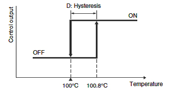 -Simple implementation.
3. PID Control (Proportional-Integral-Derivative)
A more sophisticated control technique combining three components to achieve precise and stable control.
A. Proportional (P) Control
- Definition: Applying a signal to the actuator proportional to the difference between the desired and actual values.
- Equation:
- Effect: Corrects the error, but may lead to steady-state error.
- Higher Gain leads to oscillations in signal
B. Integral (I) Control
- Definition: Integrating the difference between the desired and actual values and applying the resulting value for control. The integrated value is multiplied by a coefficient Ki.
- Equation:
- Effect: Eliminates steady-state error, but can cause overshoot and instability.
- Small changes to this filter have big effects
C. Derivative (D) Control
- Definition: Control based on the differential of the error signal.
- Equation:
- Effect: Dampens oscillations, improves stability, and responds to rate of change of the error.
PID Implementation
Set desired target Vd Increase Kp, and set values until oscillations happen. when it oscillates, divide by 2 Kp/2 Set values to Kd to increase results with 5-10% Increase Ki up to oscillations, and divide the current value with 2 or 3 , the filter coefficient. Try other values for Vd
9. Fuzzy Control in Embedded Systems: A Comprehensive Summary
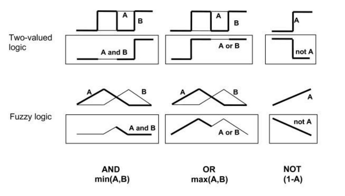
1. Fuzzy Logic
- A form of multi-valued logic, not just True or False.
- Analyzes analog inputs using logical variables with continuous values between 0 and 1.
- Extends Crisp sets using the concept of partial truth or nuance.
2. Linguistic Variables
- Used to express concepts.
- Example: In “The room temperature is HOT,” ‘HOT’ is a linguistic variable which represent the room temperature. It can represented by Fuzzy Sets
3. Key Steps
- “IF…THEN approach” which is the core concept used as fuzzy logic control technique:
- Fuzzification: Transform crisp input values into fuzzy membership values
- Rule Evaluation: Apply fuzzy logic rules
- Minimum Criterion (AND): Use the minimum value in a rule’s antecedent.
- Defuzzification: Convert the fuzzy output into a crisp control action
II. Designing a Fuzzy Logic Controller
- Fuzzification: Convert crisp inputs into fuzzy sets
- Rule Evaluation: Determine the degree to which rules are satisfied
- Defuzzification: Convert fuzzy outputs into crisp control values
III. Reasons for Using Fuzzy Logic (and When Not To)
Advantages: *IF…THEN approach” helps to implement logic Easy to be implemented
- Handles uncertainty and imprecise information.
- Models non-linear relationships.
- Intuitive to design
Disadvantages
- Requires time to calculate fuzzy logic, slower than a PID controller
- Not suited as a general-purpose knowledge base.
Operating Systems
Operating systems represents the resource management mechanism of a computing system such as memory, peripherals and processing time.
Modes of operation : • operating in the Infinite loop, • sequential systems • preemptive operating systems. • real-time operating systems - FreeRTOS.
Single-Process Mode (No OS)
Infinite loop execution Characteristics:
- One main function with infinite loop
- Sequential task execution
- CPU Load: 100% (always busy)
- No multitasking capability
wile(true) {
	taskA();
	taskB();
}
Multi-Tasking Modes
A. Cooperative Multitasking (Non-Preemptive)
Tasks voluntarily yield control Characteristics:
- Tasks must explicitly return control
- No forced interruption
- Relies on task cooperation
- Risk of system hang if task doesn’t yield
Problems:
- Spin locks waste CPU cycles
- Unresponsive tasks block system
- Poor real-time performance
B. Preemptive Multitasking
OS forcibly switches between tasks Characteristics:
- Timer interrupt-driven scheduling
- Forced context switching
- Better responsiveness
- Real-time capabilities
Advantages:
- Guarantee response times
- no task monopolization
- better cpu/memory/power utilization
- priority management
Examples: FreeRTOS (Preemptive RTOS)
- Task creation with priorities
- Scheduler with preemption
- Inter processes communication mechanisms (queues, semaphores)
- Memory management
Task Scheduling Strategies
- Time-Based Scheduling
- Fixed recurrence intervals
- Offset timing for load distribution
- Priority levels for critical tasks
- Event-Driven Scheduling
- Interrupt-triggered execution
- Asynchronous task activation
- Resource-efficient operation
- Hybrid Scheduling
- Combination of time and event triggers
- Flexible task management
- Optimized for specific applications
Diagnosis
Diagnosis is the mechanism for monitoring system functionality and generating reactions to certain situations.
Protections are mechanisms for limiting functionality depending on certain symptoms to protect the system or environment.